#diagram microcontroller
Explore tagged Tumblr posts
Visit Tumblr Blog
Explore Tumblr blogs with no restrictions, modern design and the best experience.
Last Seen Tumblr Blogs


Fun Fact
Tumblr was acquired by Yahoo for $1.1B in 2013.
Text
Our OPT4048 breakout is ready — now with a bonus web app! 🌈💻
We're wrapping up the design for the OPT4048 breakout: mostly putting the finishing touches on the Arduino library (https://github.com/adafruit/Adafruit_OPT4048). Since the whole point of this sensor is that it gives you CIE X & Y coordinates, we thought it would be cool to plot that onto a CIE diagram (https://en.wikipedia.org/wiki/CIE_1931_color_space).
Historically, we’d have to use Processing (https://processing.org/), but now you can use WebSerial to get data directly from a microcontroller!
Only catch — it’s been like 15 years since I wrote JavaScript, so we asked Claude Code (https://docs.anthropic.com/en/docs/claude-code/overview) to help out. With a little direction, it delivered a perfect demo (https://github.com/adafruit/Adafruit_OPT4048/commits/gh-pages) in about 30 minutes.
It was so fun, we’re thinking of doing WebSerial demos for more products! You can try it out by uploading the code here (https://github.com/adafruit/Adafruit_OPT4048/blob/main/examples/opt4048_webserial/opt4048_webserial.ino) and then visiting this page: https://adafruit.github.io/Adafruit_OPT4048/webserial/
5 notes
·
View notes
Text
Top Innovative STEM Lab Solutions for Schools and Colleges in 2025

In the ever-changing academic environment of today, education has no longer stayed tethered to books and lectures. Because of the real world, schools, colleges, and training institutions are heavily investing in Innovative STEM Lab Solutions to provide a balance between theory and practice. These modern setups have allowed students to hone their scientific, technological, engineering, and mathematical abilities through experimentation, problem-solving, and design thinking.
For those teachers, administrators, or institutions willing to update their infrastructure, the following are the main STEM lab solutions that will make a difference in 2025.
Modular lab stations
A modern STEM lab is, by definition, very flexible. Modular lab stations are perfect in a school where the space must sometimes be used for robotics, sometimes for chemistry, and sometimes for electronics. These stations usually have moving workbenches, moving storage, and integrated power supplies, making them perfect for interdisciplinary learning.
Why it works:
Efficient use of space
Facilitates teamwork and solo work
Adapting to different grade levels and projects
Robotics & Automation Kits
Being widely accepted in industries, automation is the need of the hour for STEM kits. Robotics kits consist of Programmable Robots, Sensors, Servo motors, and AI Integration kits that allow students to build their robots, program them, and control them.
Our Top Picks:
Arduino-based Robotics Platforms
LEGO® Education SPIKE™ Prime
Raspberry Pi + sensor modules
The kits offer an excellent opportunity to market coding and engineering skills in a manner that is both entertaining and practical.
FDM 3D Printers and Rapid Prototyping Setup
3D printers are no longer a luxury—they remain a must-have. They enable students to build their prototypes, test their mechanical models, and engage in product design. Increasingly, schools are embedding 3D printing into STEM pedagogy so that students can apply their knowledge to solve real-world problems.
Benefits:
Enhances spatial and design thinking
Promotes iteration and creativity
Encourages integration across various subjects (science and art, for instance)
Interactive Digital Boards and Simulation Tools
Chalk and blackboards are a thing of the past. Digital smart boards and simulation software enliven the abstract concepts of STEM, such as chemical reactions or circuit UML diagrams. Teachers have real-time data at their fingertips, can draw on touch screens, and engage students in solving problems together.
Combined with Arduino simulators, circuit design software like Tinkercad, or tools for virtual dissection, it makes the lab intelligent and fun.
IoT- and AI-Based Learning Modules
In 2025, IoT- and AI-based experiments will be part of every competitive mainstream STEM education. Cutting-edge labs are equipped with sensors, cloud dashboards, and microcontrollers to help students build all kinds of smart projects, such as home automation projects, temperature monitoring systems, or AI chatbots.
The solutions prepare the students to think beyond conventional science and prepare tech jobs of the future.
Curriculum-Aligned STEM Kits
Curriculum-aligned STEM kits, thus, remain relevant for teaching. These kits are uniquely designed to meet the lesson plans, experiment manuals, safety instructions, and real-world problem-based learning content required by the curriculum. They are made for specific classes and subjects with which CBSE, ICSE, IB, or state boards can identify.
Features to look for:
Subject-specific kits (Biology, Physics, Chemistry)
Safety compliance (CE, ISO certifications)
Teacher guides and student workbooks
Cloud-Based Lab Management System
Heading into 2025, cloud-based lab management platforms are becoming more and more popular. This allows instructors to track inventory, log student experiments, manage schedules, and upload student reports onto the cloud, thereby cutting down the paperwork and boosting the efficiency of the lab as a whole.
STEM-Learning Corners in Classrooms
These STEM corners in regular classrooms find favor with many schools, especially for the many that do not have the funds for the full-blown labs. Here little places house essential kits, puzzles, experiment tools, and DIY stations where students can entertain themselves exploring topics on their own.
This makes the STEM field much more approachable and far more interesting from an early age.
Conclusion
The year 2025 marks a decision point for investing in Innovative STEM Lab Solutions: choosing to invest is no longer an option but really a must. Through robotics kits, IoT modules, and modular workstations, these solutions pre-emptively prepare students for the future by instilling critical thinking, creativity, and problem-solving abilities.
If your institute is planning a STEM lab upgrade, select the supplier who understands academic requirements and contemporary technology trends. Tesca Global has earned recognition as a name offering second-to-none, affordable, and curriculum-aligned STEM lab solutions customized for schools, colleges, and universities worldwide.
#laboratory equipment suppliers#developers & startups#educational lab equipments#business#news#photography#technology
0 notes
Video
youtube
A GPRS-Based Automatic Vehicular Accident Detection and Rescue Alert System using IoT is a smart system that detects road accidents in real-time and sends alerts to emergency services and/or predefined contacts using mobile data (via GPRS). Here's a breakdown of the project concept and how you can implement it This system uses sensors to detect accidents, a microcontroller to process the data, and a GPRS module to send alerts over the internet. GPS provides location data. When an accident is detected (e.g., sudden impact or rollover), the system sends a rescue alert with vehicle location.***********************************************************If You Want To Purchase the Full Working Project KITMail Us: [email protected] Name Along With You-Tube Video LinkWe are Located at Telangana, Hyderabad, Boduppal. Project Changes also Made according to Student Requirementshttp://svsembedded.com/ https://www.svskits.in/ http://svsembedded.in/ http://www.svskit.com/M1: 91 9491535690 M2: 91 7842358459 We Will Send Working Model Project KIT through DTDC / DHL / Blue Dart We Will Provide Project Soft Data through Google Drive1. Project Abstract / Synopsis 2. Project Related Datasheets of Each Component3. Project Sample Report / Documentation4. Project Kit Circuit / Schematic Diagram 5. Project Kit Working Software Code6. Project Related Software Compilers7. Project Related Sample PPT’s8. Project Kit Photos9. Project Kit Working Video linksLatest Projects with Year Wise YouTube video Links152 Projects https://svsembedded.com/ieee_2024.php133 Projects https://svsembedded.com/ieee_2023.php157 Projects https://svsembedded.com/ieee_2022.php135 Projects https://svsembedded.com/ieee_2021.php 151 Projects https://svsembedded.com/ieee_2020.php103 Projects https://svsembedded.com/ieee_2019.php61 Projects https://svsembedded.com/ieee_2018.php171 Projects https://svsembedded.com/ieee_2017.php170 Projects https://svsembedded.com/ieee_2016.php67 Projects https://svsembedded.com/ieee_2015.php55 Projects https://svsembedded.com/ieee_2014.php43 Projects https://svsembedded.com/ieee_2013.php1600 Projects https://www.svskit.com/2025/01/1500-f...***********************************************************1. accident alert and vehicle tracking system project report,2. accident alert system ppt,3. accident avoiding system with crash detection and gps notification,4. accident detection and alert system using 8051,5. accident detection and alert system using Arduino,6. accident detection and alert system using arduino code,7. accident detection and alert system using arduino ppt,8. accident detection and prevention system,9. accident detection system project report,10. accident detection system using android application,11. accident detection system using mobile phones Wikipedia,12. accident detection using gps and gsm arduino pdf,13. accident detection using gps and gsm arduino ppt,14. accident detection using gps and gsm project report pdf,15. accident detection using mobile phones ppt,16. accident gps, gsm arduino project,17. accident prevention system for future vehicle,18. accident response system,19. advantages of accident detection and alert system,20. an iot based smart system for accident prevention and detection,21. application of accident detection system,22. arches related to wireless accident intimation system,23. Arduino based vehicle accident alert system using gps, gsm and vibration sensor,24. automatic accident detection system,25. automatic accident detection using iot,26. automatic accident report system,27. automatic vehicle accident detection and messaging system using gsm and gps modem,28. automatic vehicle accident detection and messaging system using gsm and gps modem ieee papers,29. car accident detection and reporting system,30. crash detection using accelerometer,31. intelligent accident detection and alert system for emergency medical assistance,32. iot based accident detection system,33. iot based accident prevention and tracking system,34. iot based accident prevention and tracking system,35. iot based accident prevention system,36. iot based automatic vehicle accident detection and rescue system,37. iot based vehicle tracking and accident detection system,38. iot based vehicle tracking and accident detection system pdf,39. iot based vehicle tracking system pdf,40. literature survey on accident detection,41. real time vehicle accident detection and tracking using gps and gsm,42. research paper on accident detection system43. road accident prevention using iot,44. sensor based accident prevention system,45. smart accident detection system,
0 notes
Text
Notes on Self-Studying STM32F10x Microcontroller Interrupts
Having previously used PIC and 8051 microcontrollers, I had never encountered the STM32 series of chips. Recently, I began delving into the STM32F10xseries.
During my studies, I found the STM32's interrupt system to be quite distinctive compared to those of the PIC and 8051, particularly in its response mechanism. Despite going through manuals and video tutorials multiple times, I still felt somewhat confused. However, as I began coding to configure the chip, I gradually started to understand it better. This led me to document my experiences as summary notes. I acknowledge that there may be some inaccuracies or gaps in my descriptions, and I encourage feedback and corrections.
The STM32 is built on the ARM Cortex-M3 core, which supports up to 256 interrupt sources. Out of these, 16 are core-specific, while up to 240 can be attributed to external devices. Each interrupt source has an independent priority control register, which is an 8-bit register. In theory, this means each interrupt source within a complete Cortex-M3 core could have 256 levels of priority. However, this vast architecture pertains to the entire Cortex-M3 core.
In the case of STM32 chips, not all possible interrupt sources or priority levels are used. Specifically, our STM32 model has the core's 16 interrupt sources and 68 additional sources from external devices. Since the STM32 doesn’t exploit all the interrupt sources available with the Cortex-M3, it also doesn't offer the full spectrum of 256 priority levels for configuration. Instead, the priority setting registers for each interrupt source in the STM32 use only the upper 4 bits of the 8-bit register. Details can be seen in the diagram below:↓
In STM32 microcontrollers, interrupt priorities are set using a priority register where each interrupt source has 4 bits allocated for this purpose. These 4 bits are divided into two groups: the "preemptive priority" (higher bits) and the "subpriority" (lower bits). The preemptive priority determines if an interrupt can interrupt currently executing interrupts, while the subpriority resolves conflicts between interrupts with the same preemptive priority.
The configuration of these priorities is managed by the Application Interrupt and Reset Control Register (AIRCR), specifically using bits 10, 9, and 8, known as the "PRIGROUP" bits. These bits define how the 4-bit priority is split between preemptive priority and subpriority, establishing different grouping schemes. For example, setting PRIGROUP to 101 configures the system to use 2 bits for both preemptive and subpriority levels, allowing values from 0 to 3 for each.
According to Cortex-M3 specifications, regardless of how many bits are used for priorities, the lower bits of the priority register are truncated when defining priorities. This means that when configuring priority groupings, at least one bit must be reserved for subpriority, ensuring that even if all bits are dedicated to subpriority, no nesting will occur, only sequential processing. In the STM32 priority register, typically the upper 4 bits define the priority, but during grouping, the lower 4 bits may influence the grouping scheme, such as in Group 4 where all 4 bits are assigned to preemption priority, leaving none for subpriority.
The difference between "preemption priority" and "subpriority" can be understood as follows: If multiple interrupts happen at the same time, the CPU prioritizes based on preemption priority. New interrupts with a higher preemption level can preempt ongoing ones, leading to interrupt nesting. However, if interrupts have the same preemption priority, they are processed sequentially according to their subpriority, with the lowest subpriority being handled last. If both preemption and subpriority are identical, STM32 processes the interrupt with the lower vector address first.
Interrupts in STM32 can also be in a "pending" state, which occurs when an interrupt request is made but cannot be executed immediately due to an active interrupt with equal or higher preemption priority. The pending state can be manually set using the ISPR[2] (Interrupt Set-Pending Register) and cleared using the ICPR[2] (Interrupt Clear-Pending Register). When conditions allow, a pending interrupt will be processed based on its configured priority.
TAG: STM32F10x; Electronic Components; Register
0 notes
Text
Old School Digital Frequency Counter
Frequency in physics refers to the number of oscillation periods per unit time. To measure the frequency of electrical vibrations digitally, one needs to convert the waveform into pulses and count how many of those pulses have arrived over a certain time.
The simplest way to obtain pulses from different waveforms is to use a half-wave rectifier on diode D1, followed by a parametric voltage regulator on Zener diode D2, and a resistor R1.

The Zener diode limits the signal voltage not to damage the logic chips but to keep them operational. Resistor R1 limits the operating current of the Zener diode. Resistor R2 pulls the node output to the ground to protect it from interference.
Let's recall the diagram of an electronic clock from the other post. An electronic clock is a digital pulse counter. In this case, each digit is processed by a binary decimal counter on half of the CD4158 chip, decoded by the CD4511 decoder, and displayed on a seven-segment indicator.

Shift to the next digit is also done here, accounting for the specifics of each digit: seconds and minutes are counted up to 59, and hours—up to 23.
Counting hours, minutes, and seconds is a special case because we're used to it. Supposing we need a plain pulse counter where each digit works as a standard, In that case, it goes to zero and sends a carry pulse after nine—then a much more compact solution is possible.
In an electronic clock, for every two digits, we needed three and a quarter chips: two seven-segment decoders, one dual counter, and one 2AND logic element. The CD4081 chip has four of those.
And here, for a total of three digits, two chips are enough: a counter and a decoder! Moreover, four chips and three transistors allow us to count from 000000 to 999999!

This is the primary default circuit from the datasheet for the MC4553B, a 3-digit BCD counter. We will use it today in our frequency meter. But first, let's take a closer look at the operation of this fantastic chip.

It all starts with the pulse shaper and the DISABLE input, which, as the name suggests, disables counting if the voltage level is high.
Next, we have three BCD counters, precisely the same as the CD4518 halves we've used in the digital clock.
3ANDs are used for carrying (and that's just what they do); if Q0 and Q3 are ones, that is, we have the number b1001 = 9, and the next clock pulse arrives, then a carry pulse is generated, and the counter goes to b0000 = 0.
When the chip counts to 999, and the next pulse arrives, it goes to 000 and sends a carry pulse to the OVERFLOW output.
The diagram below shows the MR (Master Reset) input. When a logical one arrives at it, all four counters are reset, as well as the scanner, which we will cover a little later.
Next, we see three 4-bit latch registers. We discussed a shift register with a latch function thoroughly in the post. To be brief, the register is 'transparent'. It simply transmits data from the inputs to the outputs as long as the input LE (LATCH ENABLE) is low.
A logical one at LE makes the register stop responding to the state of the inputs, saving the stored states at the outputs.
This is an excellent feature for meters with indicators because it allows the readings to be frozen so that a person can actually read them.
Flip-flops are also used, for example, in analog-to-digital conversion, to preserve the finished, complete result and not confuse it with the intermediate one. Latches are also a necessity for data communication modules.
If you program microcontrollers, then you probably know that their peripheral architecture contains many latched registers, and the code often interacts with them.
This is very convenient, allowing asynchronous peripherals to work independently without adding processing load and wasting program memory. And if and when an interrupt or a flag state indicates the presence of a ready result, the program can start processing it.
Data from the outputs of three four-bit latching registers is supplied to a multiplexer controlled by the scanner.
This scanner is a counter-decoder, similar to our trusty CD4017. Only the CD4017 counts from 0 to 9, and the scanner counts from 0 to 2 or 1 to 3, whichever you prefer best.
The scanner is clocked by an oscillator, and the oscillation frequency is set by capacitor C1. And if this capacitor is absent, then clocking can be done from an external source.
So, at the outputs Q0..Q3, we will have a binary representation of a digit, and the number of this digit, the register, is output to the ¬DS1..¬DS3. We'll have a low level at a single output, corresponding to the position of the output digit.
With the help of a multiplexer and a scanner, we can get by with just one seven-segment decoder for three bits! We use MC14543B here, and it works exactly like the CD4511 in the clock application.
This economical way of displaying the digits, when they are shown one after another, is called dynamic and is very often used in projects with microcontrollers.
In this diagram, we see that all six indicators are activated by three transistors from the left MC14553B chip. The scanner on the correct chip is synced with clock pulses from the left one.
And for each of the three-digit decimal counters to start outputting readings from the same first digit, the MR input (MASTER RESET) resets the scanner and the counting registers.
So, we connected our two-diode pulse shaper to the CLOCK INPUT and got ourselves a pulse counter from 0 to 999999.
To turn this counter into a frequency meter, we need to program the following sequence:
Perform a master reset of both counters.
Allow the counters to count pulses for one second.
Latch the indicators for three and a half seconds so they can be read.
Go to step 1.
Do we need a microcontroller, then? Not really; a sequencer can handle such a simple task.
Here, we have a quartz-stabilized clock generator that produces a frequency of 2 hertz, precisely the same as in our homemade clock. And the role of the sequencer is played by our beloved CD4017; it just needs some help from eight diodes.
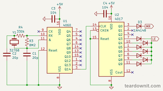
When output Q0 is high, our pulse counter gets a master reset. Then, a second passes until the logical one moves to Q1 and then to Q2. It is not output anywhere; the counter continues to count for itself.
As soon as a second has passed, the counter has registered the number of pulses corresponding to the input signal frequency. Then, the logical one from Q3 sends the LATCH ENABLE signal.
The pulse counter continues to count, but this does not affect the indicator readings, and they stay put for three and a half seconds.
Then, the logical one is once again at Q0, a master reset occurs, and the cycle repeats.
This is how our DIY frequency meter works, which we've managed to program using just diodes and no microcontroller.
0 notes
Text
Arduino Projects
Arduino is a platform for microcontrollers, but it's also a doorway to infinite innovation and creativity. Arduino projects are a great way to realize ideas, pick up new skills, and solve practical problems, regardless of your level of experience as an engineer, student, or hobbyist.
Why Arduino?
Easy to Use: Beginners can now easily learn hardware programming thanks to Arduino boards, which are plug-and-play gadgets.
Affordability: Arduino boards and parts are reasonably priced, which makes them perfect for do-it-yourselfers and educational institutions.
Flexibility: Arduino can be tailored to a variety of applications because of its extensive selection of sensors, actuators, and shields.
Community Support: To guarantee that assistance is always available, a global community of developers exchanges forums, tutorials, and open-source projects.
Popular Arduino Projects
Smart Home Automation
Weather Station
Robot Car
IoT Plant Monitoring System
Security Alarm System
LED Light Displays
Wearable Tech
Getting Started with Arduino Projects
Select Your Board: For novices, the Arduino Uno is a fantastic option. Think about using an Arduino Mega or Nano for more complex projects.
Acquire the Fundamentals: Learn the fundamentals of C/C++ programming with the Arduino IDE (Integrated Development Environment).
Start Small: Start with easy projects like reading temperature sensor data or making an LED blink.
Develop Your Skills: Learn about other parts like motors, LCDs, and connectivity modules like Bluetooth or Wi-Fi.
Leverage Resources: To learn and troubleshoot, consult online tutorials, project instructions, and community forums.
Record Your Work: Maintain a record of your efforts, including observations, circuit diagrams, and code.
Arduino projects provide access to countless possibilities in the fields of IoT, robotics, and do-it-yourself electronics. They aim to develop creativity, inventiveness, and problem-solving abilities in addition to developing devices. Every project advances your learning and exploration, whether you're automating your entire house or just lighting up an LED.
To know more, click here.
0 notes
Text
Fire Detection and Alarm System for Home and Industrial Safety
Introduction Project Overview Components Used Circuit Diagram and Working Principle Step-by-Step Guide Applications Benefits Conclusion Introduction Fire Detection and Alarm System for Home and Industrial Safety is an innovative project designed to detect potential fire hazards and alert users in real-time. Utilizing an Arduino UNO microcontroller, sensors, and a relay module, this system…
0 notes
Text
Register Datasheet: The Power of Smart Datasheet Management

In today’s data-driven world, the efficiency with which we manage and access information plays a pivotal role in success, especially in industries dealing with vast amounts of data. A register datasheet, or more broadly, a smart datasheet, provides an innovative solution to streamline data handling, improve accessibility, and reduce manual errors. These smart datasheets have revolutionized traditional data management systems by embedding dynamic features and ensuring a high level of adaptability for modern businesses. This article explores the concept of a register datasheet, its features, advantages, and its significance in today’s digital landscape.
What is a Register Datasheet?
A register datasheet refers to a document that lists and defines all the internal and external registers associated with a hardware device, such as a microcontroller or an FPGA (Field Programmable Gate Array). These registers store critical control data, configuration settings, and real-time operational information, enabling the device to function optimally. Traditional register datasheets were static, often in the form of PDFs or spreadsheets, that engineers and developers would use for reference during system design, development, and troubleshooting.
However, as systems have grown more complex, the demand for more smart datasheets has increased. A smart datasheet is an advanced digital version of a traditional datasheet. It’s interactive, dynamic, and integrated with automated functionalities, allowing for real-time updates, searchability, and easy data manipulation.
Features of a Smart Register Datasheet
Interactive Interface: A smart datasheet offers a user-friendly, interactive interface. Instead of scrolling through endless pages of static data, users can click through sections, filter specific details, or jump to relevant data points instantly.
Real-Time Updates: Unlike traditional datasheets that require manual updates, smart datasheets integrate directly with the data source, ensuring that all information remains up-to-date in real time. For instance, when a new hardware version or firmware update is released, the smart datasheet reflects the changes immediately.
Search and Filter Capabilities: Smart datasheets allow users to search for specific registers or configuration options quickly. Advanced filter options let users narrow down to relevant data, saving time and reducing human error when interpreting or extracting data.
Data Visualization: Visual aids such as charts, graphs, and diagrams are embedded directly into the smart datasheet. These visual representations help engineers better understand the data, track device performance, and compare configurations.
Export and Import Functions: Users can export sections or the entire datasheet into various formats (CSV, XML, PDF) for further analysis. Additionally, smart datasheets allow importing external data to match configurations or perform comparative analysis with existing systems.
API Integration: Smart datasheets often come with API (Application Programming Interface) support, allowing external software or tools to interact directly with the datasheet, retrieve specific data, or push updates.
Advantages of Smart Datasheets
Enhanced Efficiency and Productivity: The interactive nature of smart datasheets reduces the time spent on searching, interpreting, and analyzing data. Engineers no longer need to comb through pages of static text but can access the exact data they need within seconds. This efficiency improves overall productivity, especially in fast-paced environments where timely access to information is crucial.
Improved Accuracy: Manual handling of datasheets often leads to errors, such as misreading registers or applying outdated configuration settings. Smart datasheets eliminate these risks by ensuring all data is accurate and updated automatically. With real-time synchronization, there is no risk of working with outdated specifications.
Customization and Flexibility: Smart datasheets allow for greater customization, enabling users to view data in a format that suits their specific requirements. Whether it’s a specific device configuration, register layout, or operational data, users can tailor the datasheet view to suit their needs. This flexibility makes it easier to manage complex data and adapt to changing project requirements.
Collaboration and Sharing: Smart datasheets enable easy sharing and collaboration among teams. Cloud-based smart datasheets allow multiple users to access, update, or comment on the document in real time. This collaborative approach improves communication within teams and across departments, ensuring everyone is working with the latest and most accurate data.
Integration with Development Tools: Modern smart datasheets integrate seamlessly with development environments and tools such as Integrated Development Environments (IDEs), simulators, or test benches. This tight integration allows engineers to test configurations, simulate behavior, or verify performance directly from the datasheet, enhancing the development workflow.
Importance in the Digital Age
In the era of IoT, AI, and advanced automation, hardware devices are becoming increasingly sophisticated. As a result, the datasheets associated with these devices are more detailed and complex than ever before. Traditional static datasheets simply can't keep pace with the rapid development cycles and growing complexity of modern devices.
Smart datasheets address this challenge by providing dynamic, real-time access to critical data in a format that is both flexible and easy to use. This ensures that engineers and developers have the tools they need to make informed decisions, minimize errors, and accelerate time to market.
Moreover, as remote work and digital collaboration become more prevalent, cloud-based smart datasheets ensure that all stakeholders, regardless of location, have access to the latest data, facilitating better coordination and decision-making.
Conclusion
The register datasheet has evolved from a simple static reference document into a powerful, smart tool for managing complex data. With its interactive interface, real-time updates, search capabilities, and seamless integration, a smart datasheet provides significant advantages in terms of efficiency, accuracy, and collaboration. As industries continue to embrace digital transformation, adopting smart datasheets will become increasingly essential for businesses looking to stay ahead in a competitive, data-driven landscape.
0 notes
Text
Arduino UNO R3 DIP with ATmega328P

Are you looking to buy the Arduino Uno R3 CH340G ATMEGA328P Development Board for your next Arduino project?
Don’t look any further! Ainow, your trusted electronic component supplier in India, offers you this exceptional development board, fully compatible with Arduino Uno R3 projects. In the world of electronics and programming, the Uno R3 CH340G ATMEGA328P Development Board is more than just a microcontroller board; it’s a gateway to endless possibilities.
This board is engineered with precision and durability to meet the needs of both beginners and experienced enthusiasts. Its versatility knows no bounds – whether you’re into robotics, IoT, home automation, or creative automation projects, this board is perfect.
Even new Arduino users will find it easy to use, thanks to the plug-and-play design and user-friendly interface. This development board’s ATmega328P microcontroller and CH340G USB-to-serial converter chip make sure seamless data transfer and efficient performance. You’ll be amazed at how fast your Arduino projects will run with this board.
we believe in offering the best value for your investment. You can buy the Uno R3 CH340G ATMEGA328P Development Board for a competitive price, with no hidden charges. Our nationwide shipping ensures your order reaches you in perfect condition and in the fastest time possible.
We detail Arduino code for making a smart dustbin, the required components, and the circuit diagram for making an automatic dustbin in our blog smart dustbin project using Arduino.
For using this Uno R3 Board compatible with Arduino in your small or DIY projects, you will need some essential components, such as
Breadboard
Wire jumpers
Power supply or batteries
Motors made by BO
Drivers of motor vehicles
The sensors
Check out the Arduino Uno R3 compatible board
1 note
·
View note
Text
Mastering PCB Reverse Engineering: Unlocking the Secrets of Complex Circuitry
In the world of electronics, the demand for precise, efficient, and high-quality PCB (Printed Circuit Board) reverse engineering services is growing exponentially. This intricate process involves deconstructing a PCB to uncover its design, components, and functionality, enabling the replication or modification of complex electronic systems. Let's delve into the fascinating realm of PCB reverse engineering and explore its multifaceted services and applications.
The Expertise in PCB Reverse Engineering
Experts in PCB reverse engineering leverage professional software and advanced techniques to achieve a 100% success rate in copying and modifying PCBs. These specialists handle high-difficulty and multi-layer PCBs with blind holes, ensuring the cloned boards are indistinguishable from the originals.
Unlocking IC Chips
One of the standout services in PCB reverse engineering is the ability to unlock various IC (Integrated Circuit) chips. This includes MCUs (Microcontroller Units) from brands like ARM, STM32, GD32, Samsung, RENESAS, NEC, and TI. The unlocking process is meticulously executed without damaging the original chips, allowing for seamless integration and functionality in secondary electronic product development.
Comprehensive PCBA and SMT Services
PCB reverse engineering goes beyond mere replication. It encompasses a full suite of services, including:
PCB Design: Crafting new designs or modifying existing ones based on reverse-engineered data.
Sample Debugging: Ensuring the prototypes function correctly before mass production.
PCBA Welding: Precision welding for secure component attachment.
Component Selection and IC Procurement: Sourcing high-quality components to match the original design.
High-Precision Board Making: Producing boards with exact specifications to meet industry standards.
SMT Chip Processing: Surface Mount Technology (SMT) for efficient and compact component placement.
Accurate PCB Copy and Modification
Specialists in PCB reverse engineering can clone single-layer, double-layer, and multi-layer PCBs, up to 32 layers. This includes handling complex designs with blind holes. The cloning process guarantees a one-time success rate, producing circuits identical to the original. Modifications can be made as per customer requirements, ensuring the final product meets precise specifications.
BOM List Creation and Procurement
A crucial aspect of PCB reverse engineering is generating an accurate Bill of Materials (BOM). Utilizing professional precision measuring instruments, experts can quickly and accurately identify the model and parameters of original components, provided the device markings are legible. This results in standardized and complete BOM lists, streamlining the procurement process and ensuring the availability of necessary components.
Deriving Schematic Diagrams
Based on the original PCB or its file, reverse engineering experts can accurately derive the PCB schematic. This includes detailed information on component location numbers, models, and network names. The readability and clarity of these schematics are on par with original design drawings, facilitating easy modifications and verifications for customers.
PCB Sample and Batch Production
The production capabilities in PCB reverse engineering are vast, encompassing high-density, high-precision single-sided, double-sided, and multi-layer rigid and flexible PCBs. These services support up to 32-layer PCB production, with minimum laser and mechanical apertures of 4mil and 8mil, respectively. Additionally, the production process can incorporate embedded blind holes, catering to the most complex designs.
PCB reverse engineering is a sophisticated and essential service in modern electronics, enabling the precise replication, modification, and enhancement of intricate circuit boards. With a comprehensive suite of services ranging from IC unlocking to schematic diagram derivation and high-precision production, PCB reverse engineering paves the way for innovation and excellence in the electronic industry.
0 notes
Text
Essential Topics for the FE Electrical & Computer Exam: What You Need to Know
Preparing for the Fundamentals of Engineering (FE) Electrical and Computer exam can be a daunting task, but with the right resources and a well-structured study plan, success is within your reach. Our FE Electrical Exam Course is designed to equip you with the knowledge and confidence needed to excel in this critical exam. Here, we’ll outline the essential topics you need to master for the FE Electrical and Computer exam.
Mathematics
Mathematics forms the backbone of the FE Electrical and Computer exam. Topics you must be proficient in include calculus, linear algebra, differential equations, and probability and statistics. These mathematical principles are not only crucial for solving direct questions but also for understanding complex engineering problems.
Key Areas to Focus On:
Calculus: Limits, derivatives, integrals, and their applications.
Linear Algebra: Matrix operations, vector spaces, and eigenvalues.
Differential Equations: First-order and higher-order differential equations.
Probability and Statistics: Probability distributions, mean, median, mode, and standard deviation.
Circuits
A solid understanding of electrical circuits is essential. This includes both DC and AC circuits, where you’ll need to analyze and design various circuit configurations.
Key Areas to Focus On:
DC Circuits: Ohm’s Law, Kirchhoff’s Laws, and circuit analysis techniques.
AC Circuits: Impedance, phasors, and resonance.
Power Analysis: Real, reactive, and apparent power calculations.
Circuit Theorems: Thevenin’s and Norton’s theorems, superposition, and maximum power transfer.
Electronics
Electronics is another critical area, encompassing both analog and digital systems. You’ll need to understand the behavior of semiconductor devices and their applications in circuits.
Key Areas to Focus On:
Semiconductor Theory: PN junctions, diodes, and transistors.
Amplifiers: Operational amplifiers and their configurations.
Digital Logic: Logic gates, Boolean algebra, and combinational and sequential logic circuits.
Microcontrollers: Basic understanding of microcontroller functionality and applications.
Electromagnetics
Electromagnetics covers the study of electric and magnetic fields and their interactions. This is fundamental to understanding wave propagation and transmission lines.
Key Areas to Focus On:
Electrostatics: Electric fields, potential, and capacitance.
Magnetostatics: Magnetic fields, inductance, and magnetic materials.
Transmission Lines: Characteristic impedance, reflection, and transmission coefficients.
Maxwell’s Equations: Their application in engineering problems.
Control Systems
Control systems are integral to modern electrical and computer engineering, involving the design and analysis of systems that maintain desired outputs despite disturbances.
Key Areas to Focus On:
System Modeling: Transfer functions, block diagrams, and state-space representations.
Stability Analysis: Routh-Hurwitz, Nyquist, and Bode plots.
Controller Design: PID controllers, root locus, and frequency response methods.
Signal Processing
Signal processing involves analyzing, modifying, and synthesizing signals such as sound, images, and scientific measurements.
Key Areas to Focus On:
Fourier Analysis: Fourier series and transforms.
Sampling Theory: Nyquist criterion and aliasing.
Filters: Design and analysis of analog and digital filters.
Signal Modulation: AM, FM, and digital modulation techniques.
Communications
Communication systems are crucial in transferring information across various media. Understanding the fundamentals of analog and digital communication is vital.
Key Areas to Focus On:
Modulation Techniques: Amplitude, frequency, and phase modulation.
Information Theory: Entropy, data compression, and channel capacity.
Error Detection and Correction: Coding techniques and algorithms.
By focusing on these essential topics, you can ensure a comprehensive understanding of the material covered in the FE Electrical and Computer exam. Our FE Electrical Exam Course provides detailed lessons, practice problems, and expert guidance to help you master these subjects and succeed on your exam. Start your preparation today and pave the way for a successful engineering career.
1 note
·
View note
Text
Start Your Career Journey: Embedded System Pay After Placement Course
Sign up for our groundbreaking Embedded System Pay After Placement Course and venture out towards a rewarding career with Embedded Box. Our far reaching program is intended to outfit aspiring engineers with the abilities and information expected to succeed in the cutthroat field of embedded systems. At Embedded Box, we invest wholeheartedly in offering a novel mix of expert instruction, involved projects, advanced curriculum, and guaranteed placement valuable open doors with reputed organizations, setting the stage for our understudies' prosperity.
Key Highlights of our Embedded System Pay After Placement Course:
1. Expert Faculty: Gain from industry experts with broad involvement with embedded systems and gain important insights from old pros committed to nurturing the gifts of the future.
2. Live Projects: Apply hypothetical information to functional situations and gain involved insight by working on live projects, honing your critical thinking abilities and preparing for certifiable difficulties.
3. Advanced Curriculum: Remain on the ball with our carefully planned curriculum, covering the latest industry trends, technological advancements, microcontroller programming, embedded software development, and that's just the beginning.
4. Guaranteed Placement: Advantage from our novel Pay After Placement model, which offers understudies the chance to invest in their schooling with practically no financial weight forthright. Upon effective placement, understudies can then continue to pay the course expense, providing a pathway to acquiring invaluable abilities in the field of embedded systems.
5. Reputed Company Placements: Produce your career way with certainty, knowing that our Embedded System Pay After Placement Course opens ways to placement open doors with prestigious organizations in the embedded systems industry, facilitating consistent progress from homeroom learning to proficient achievement.
Join Embedded Box and quickly jump all over this chance to set out on an extraordinary learning venture that will furnish you with the expertise and experience expected to flourish in the realm of embedded systems. With our industry-aligned curriculum, committed faculty, and the confirmation of placement with respectable organizations, you can diagram a course toward a fruitful and fulfilling career in embedded systems without the financial constraints commonly connected with instructive investment.

#payafterplacementcourses#embedded system courses#embedded system embedded systems#embedded system course
0 notes
Quote
Build circuits using a variety of components from different manufacturers, like microcontrollers, memory, logic gates, and LCD screens. Write code in a compact and powerful assembly language where every instruction can be conditionally executed. Read the included manual, which includes over 30 pages of original datasheets, reference guides, and technical diagrams. Get to know the colorful cast of characters at your new employer, 深圳龙腾科技有限公司 (Shenzhen Longteng Electronics Co., Ltd.), located in the electronics capital of the world. Get creative! Design and test your own games and devices in the sandbox. Engineering is hard! Take a break and play a brand-new twist on solitaire.
SHENZHEN I/O on Steam
0 notes
Video
youtube
The GPRS-Based Smart Medicine Reminder is a microcontroller-based health monitoring system designed to assist individuals—especially the elderly, patients, and busy professionals—in remembering their medication schedules. This intelligent system combines the functionality of an RTC (Real-Time Clock), Arduino, GSM/GPRS Module, and Voice Playback to deliver timely medicine reminders using audio alerts, SMS notifications, and automated voice calls. This innovative solution ensures that a user never misses a dose by triggering alerts at pre-set times throughout the day. The system is designed to be user-friendly, reliable, and portable, making it suitable for home or clinical environments.***********************************************************If You Want To Purchase the Full Working Project KITMail Us: [email protected] Name Along With You-Tube Video LinkWe are Located at Telangana, Hyderabad, Boduppal. Project Changes also Made according to Student Requirementshttp://svsembedded.com/ https://www.svskits.in/ http://svsembedded.in/ http://www.svskit.com/M1: 91 9491535690 M2: 91 7842358459 We Will Send Working Model Project KIT through DTDC / DHL / Blue Dart We Will Provide Project Soft Data through Google Drive1. Project Abstract / Synopsis 2. Project Related Datasheets of Each Component3. Project Sample Report / Documentation4. Project Kit Circuit / Schematic Diagram 5. Project Kit Working Software Code6. Project Related Software Compilers7. Project Related Sample PPT’s8. Project Kit Photos9. Project Kit Working Video linksLatest Projects with Year Wise YouTube video Links152 Projects https://svsembedded.com/ieee_2024.php133 Projects https://svsembedded.com/ieee_2023.php157 Projects https://svsembedded.com/ieee_2022.php135 Projects https://svsembedded.com/ieee_2021.php 151 Projects https://svsembedded.com/ieee_2020.php103 Projects https://svsembedded.com/ieee_2019.php61 Projects https://svsembedded.com/ieee_2018.php171 Projects https://svsembedded.com/ieee_2017.php170 Projects https://svsembedded.com/ieee_2016.php67 Projects https://svsembedded.com/ieee_2015.php55 Projects https://svsembedded.com/ieee_2014.php43 Projects https://svsembedded.com/ieee_2013.php1600 Projects https://www.svskit.com/2025/01/1500-f...***********************************************************1. Smart Medicine Reminder Box | e-pill Medication Reminders,2. MeDuino - Automatic Medicine Reminder. Arduino diy,3. Medicine Reminder using Arduino by Saddam Khan,4. Smart Medicine Box,5. Arduino Uno based Medicine reminder project,6. Pill Reminder with Arduino version,7. Automatic patient medicine reminder system || Best project center in Bangalore,8. Automatic Pill Reminder Using Arduino uno,9. Raspberry Pi Based Speaking Medication Reminder Project,10. IoT Based Smart Medicine Box,11. Medicine Reminder simulation on proteus,12. Automatic Medicine Reminder with date using Arduino,13. Medicine reminder,14. Smart Medicine Pill Reminder IOT Project using Aurdino,15. Medicine Reminder Box Using Arduino,16. Smart Medicine Dispenser,17. Medicine reminder/Alarm using Arduino,18. MedBox: Smart Medication Box with Arduino - self test,19. Medicine Reminder System | Smart Medicine Pill Reminder Project,20. Medicine reminder using Arduino,21. Best Medicine Reminder DIY,22. Explanation of our Medicine Reminder Project,23. SmartSF Smart Pill Box,24. Medication Reminder using PIC Microcontroller,25. Medicine Reminder Using Home Made Arduino,26. Medicine Reminder System Using Microcontroller,27. ANDROID APP BASED SMART MEDICATION REMINDER SYSTEM,28. IOT Based Medicine Reminder System with Email Alert,29. Simulation: Photoresistor-based Smart Pill Dispenser | Schematic Diagram, Arduino Code
0 notes
Text
Personalised DIY E-Paper Clock Using ESP32 Microcontroller
0 notes
Text
Between Analog and Digital: Comparators

Sometimes, there's a need to compare two voltages. A special circuitry stage exists to serve just this purpose—a comparator. Today, I will tell you all about comparators and show a few examples of their use.
What is the field of application for comparators? — It is literally any device; many microcontrollers have built-in comparators of their own!
Remember our post on PWM (https://teardownit.com/posts/pwm-led-dimmer)? That circuit used as many as two comparators—U1A and U2B.

What could be simpler than a comparator? It compares two voltages at its two inputs, and based on the result of this comparison, it connects its output to the positive or negative power line.
When the voltage at the non-inverting input is higher than at the inverting input, it will be a positive supply voltage line and, accordingly, a high voltage level, a logical one. Otherwise, it will be a negative power line, a low level, or a logical zero.
Why does the comparator look like an op-amp in the diagram? Most often, this is the operational amplifier.
U1A switches the timing capacitor C1 to charge or discharge, depending on the voltage at point C, which comes to the non-inverting input of the comparator through resistor R10.
Let me draw your attention to resistor R9, as it is of great importance in this scheme.
We are accustomed to connecting a resistor between an op-amp's output and the inverting input to set the gain. This is negative feedback.
The output of U2A is connected to its inverting input. We should recall two fundamental principles of the operation of an operational amplifier: virtually no current flows through its inputs, and the output voltage, with negative feedback present, will be such that the voltages at the inverting and non-inverting inputs are equal.
Thus, the voltage at the output will equal the voltage at the non-inverting input. We've got a buffer—a voltage follower.
Why do we need such a buffer? Because the input impedance of the operational amplifier is very high, and the output impedance is low.
That means we can transmit input voltage to the load that requires a significant current and simultaneously not overload the circuit generating this voltage and not distort its operation.
And here is a small part of the Fulltone OCD guitar pedal circuit from our post about DIY Dumble-like sounding MOSFET Overdrive. The operational amplifier no longer repeats but amplifies the input voltage.

For simplicity's sake, let's ignore capacitors, although they contribute to impedance. We have to understand the core principle.
The amplifier input is the left terminal of resistor R10. To pull up the non-inverting input of the op-amp to virtual ground, which is half the supply voltage, resistor R12 is used.
R10 and R12 form a voltage divider. The voltage at the non-inverting input will equal the input multiplied by R12 / (R10 + R12) = 220 / 230 = 22/23.
22/23 is almost 1, so we'll assume that the voltage at the non-inverting input, and therefore at the inverting input, is equal to the input.
R13 and R11 are also voltage dividers in the feedback circuit of the operational amplifier. The output voltage will equal the input voltage multiplied by (R13 + R11) / R11 = 189 / 39 = 4.85. Or 4.64, if you insist on multiplying by 22/23.
Let's get back to the PWM regulator circuit. Here, we have the same voltage divider but in a stage of positive rather than negative feedback! And it is assembled with resistors R9 and R10.
Almost no current flows through the inputs of an op-amp; it only goes through R9 and R10. And since this is the same current (let’s denote it as 'I'), we can write the equations of Ohm’s law for resistors R9 and R10.
Let's say the input voltage at the correct pin of R10 is Uin, and the output voltage at the output of U1A is Uout. Call the potential of the non-inverting input U1A 'U', and we obtain the following equations:.
I = (Uout - U) / R9 I = (U - Uin) / R8
Next, we transform our equations to calculate the dependence of U on Uin.
(Uout - U) / 5.6 = (U - Uin) / 2
For simplicity, let's round 5.6 up to 6.
(Uout - U) / 3 = U - Uin Uout - U = 3U - 3Uin 3Uin = 4U - Uout U = 3/4Uin + Uout / 4
To understand what Vout might be equal to, we need to refer to the datasheet for the LM358 chip from Texas Instruments.

Our PWM controller has a bipolar power supply of +12 V and -12 V, for a total of 24 volts. These are our power bus voltages. However, due to its design characteristics, the deviation of the operational amplifier's output voltage also depends on the output current.
The load U1A is a parametric voltage stabilizer based on a two-anode Zener diode assembled from two conventional Zener diodes connected in a back-to-back series.
The forward voltage across the Zener diode at the standard shunt regulator current is 0.7 volts. Then, the correct pin of R8 will have a voltage of 5.8 volts with a plus or minus sign, depending on the polarity of the U1A output.
That means the current through R8 will be about 5 milliamps. Then Vout can be somewhere between + (12 - 1.5) = +10.5 V and - (12 - 0.75) = - 11.25 V.
So, when the logic level at the output of the comparator is high, then U = 3/4Uin + 2.63V. When the logic level is low, U = 3/4Uin - 2.8 V.
The potential of the comparator's inverting input is zero since it is connected to the ground through resistor R11.
We need the voltage at the non-inverting input below zero volts to switch the comparator from high to low. And from low to high—above zero volts. Then we get the following equations:
3/4Uin + 2.63V = 0 Uin = -3.5 V
3/4Uin - 2.8 V = 0 Uin = 3.75 V
What will then happen to the comparator in the input voltage range of -3.5 to +3.75 volts? Nothing; the comparator will not change its state.
If its output is high, it will remain high until the input voltage drops below -3.5 volts. And if it was low, then it would wait for the voltage to rise above +3.75 V to switch to high. This means the comparator has so-called hysteresis.
Comparator hysteresis is excellent for protecting against false alarms and interference. And thanks to positive feedback, we got a comparator with memory!
It saves its state and waits for the signal to be set to high or reset to low. It sounds like an RS flip-flop, right?
Sometimes, lathes are actually assembled this way. Suppose an extra comparator or an operational amplifier is left unused in some chip, and we need a flip-flop. Why add an extra element when we already have almost everything we need? Just bring in a couple of resistors.
We have an extra operational amplifier in our PWM regulator. It is U2A, which we've used as a buffer, even though the input impedance of U2B is precisely the same without a repeater. If we needed an RS flip-flop in this circuit, we could easily build it on U2A.
Now, let's build an electronic thermometer with an LED scale.

The temperature sensor is a thermistor TH1 with a negative temperature coefficient. Together with R10, they form a voltage divider.
With TH1's nominal resistance of 10 kOhm, the voltage at the resistor will be 1/11 of the supply voltage, approximately 0.5 volts.
With a total resistance of tuning resistor R9 of 100 kOhm, there will also be approximately 0.5 volts at the left pin of R1. As the resistance R9 decreases, this voltage will increase to 5 volts.
The resistive ladder R1-R8 generates a series of voltages in increments of 1/8 of the voltage at the left pin of R1.
As the temperature of the thermistor increases, its resistance will decrease. Accordingly, the voltage at the non-inverting inputs of the comparators will increase. The higher this voltage is, the more comparators will switch to a high output state, and accordingly, more LEDs will light up.
Resistance R9 can be adjusted so that D4 and D5 correspond to the desired temperature range. If D6 is not lit, the temperature is too low, and if D3 is lit, the temperature is too high.
This thermometer can serve not only as a temperature indicator but also as a temperature regulator. For example, you can do this:
When D6 goes out, the heating turns on, and when D5 lights up, it turns off.
When D3 lights up, ventilation is turned on; when D4 goes out, it turns off. This will provide hysteresis so the heater and fan do not turn on and off too often.
This is another application of hysteresis for which RS flip-flops come in handy. We already know they can be built on identical operational amplifiers in comparator mode.
The terminals for the outer LEDs (D1 and D8) can be connected to an alarm signal. Suppose the temperature in the terrarium or other place where we've installed the thermostat significantly exceeds the permissible limits. In that case, an alarm siren goes off, an SMS is sent to the phone, and so on.
So, with the help of comparators, one can turn analog values into logical events and organize automated control with a convenient visual indication.
At the same time, we did not need any microcontroller; two LM324 chips were just enough.
The operation and assembly process of the electronic thermometer are shown in the video.
0 notes